


Digitilt® inclinometers are used to monitor subsurface movements of earth in landslide areas and deep excavations.
They are also used to monitor deformations in structures such as dams and embankments.
| Operation | ||||
| Inclinometer casing is typically installed in a vertical borehole that passes through suspected zones of movement into stable ground. The Digitilt inclinometer probe, control cable, pulley assembly, and readout are used to survey the casing. The first survey establishes the initial profile of the casing. Subsequent surveys reveal changes in the profile if ground movement occurs. During a survey, the probe is drawn upwards from the bottom of the casing to the top, halted in its travel at 0.5 m or 2' intervals for tilt readings. The inclination of the probe body is measured by two force-balanced, servo-accelerometers. One accelerometer measures tilt in the plane of the inclinometer wheels, which track the longitudinal grooves of the casing. The other accelerometer measures tilt in the plane perpendicular to the wheels. Inclination measurements are converted to lateral deviations, as shown in the drawing below. Changes in deviation, determined by comparing current and initial surveys, indicate ground movement. Plotting changes in deviation yields a high resolution displacement profile. Displacement profiles are useful for determining the magnitude, depth, direction, and rate of ground movement. | 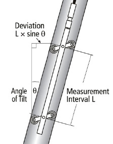 | |||
| Advantages | |||
| Proven Performance: Digitilt inclinometer probes have earned a world-wide reputation for durability, high precision, and rapid response. Repeatable Tracking: To ensure consistent tracking in all types of casing, the probe is equipped with robust wheel carriages, sealed wheel bearings, and specially designed wheels. Extended Installation Life: The compact size of the Digitilt probe allows it to pass through small radius curves, extending the useful life of the installation beyond that provided by other inclinometer probes. Computerized Testing: Each probe undergoes thorough testing on a computerized calibration table. Reliable Control Cable: Digitilt control cable is durable and easy to handle, stays flexible in cold weather, resists chemicals and abrasion, and provides excellent dimensional stability. Flexible rubber depth marks are permanently vulcanized to the cable jacket. The marks cannot loosen and have no rigid edges that can damage the cable jacket and conductors. Consistent Depth Control: The pulley assembly, a recommended accessory, helps the operator achieve uniform depth control. The one-way action of its cable clamp ensures consistent positioning of the probe. Complete Solutions: The inclinometer system includes high-quality casing, vertical and horizontal traversing probes, vertical and horizontal in-place sensors, recording readouts, graphing software, and specialized accessories. | |||
| DIGITILT INCLINOMETER PROBE | ||||
| Metric-Unit Probe | SI50302510 | |||
| English-Unit Probe | SI50302500 | |||
| Digitilt inclinometer probe includes a carrying case and instruction manual. Control cable, pulley, and readout are not included. | ||||
| METRIC PROBE SPECIFICATIONS | ||||
| Wheel base: | 500 mm | |||
| Range | ±53° from vertical | |||
| Resolution | 0.02 mm per 500 mm | |||
| Repeatability | ±0.01% FS | |||
| Calibration | 14 point calibration with NIST traceable calibration device | |||
| Temperature Rating | -20 to +50 °C | |||
| Dimensions | 25.4 x 653 mm. Control cable connector adds 92 mm to length of probe. | |||
| Weight | 1.8 kg | |||
| Material | Stainless steel | |||
| ENGLISH PROBE SPECIFICATIONS | ||||
| Wheel base | 24" | |||
| Range | ±35° from vertical | |||
| Resolution | 0.0012 inch per 24 inches | |||
| Repeatability | ±0.01%FS | |||
| Calibration | 14 point calibration with NIST traceable calibration device | |||
| Temperature Rating | -4 to +122 °F | |||
| Dimensions | 1 x 30". Control cable connector adds 3.75"to length of probe | |||
| Weight | 4 lb. | |||
| Material | Stainless steel | |||
| ACCURACY SPECIFICATIONS | ||||
| Metric Systems | ±0.25 mm per reading and ±6 mm per 50 readings | |||
| English Systems | : ±0.01 inch per reading and ±0.3 inch per 50 readings. | |||
| These system accuracy specifications were derived empirically from the analysis of a large number of surveys and include both random and systematic errors introduced by casing, probe, cable, readout, and operator. Casing was installed within 3 degrees of vertical, and operators followed recommended reading practices. When corrections for systematic error are made, the remaining error is random. It accumulates with the square root of the number of readings. Thus the best precision obtainable with a metric system is approximately ±1.4 mm per fifty readings, and the best precision of an English unit system is approximately ±0.05 inch per fifty readings. | ||||
| CONTROL CABLE | ||||
| 30m Control Cable, Complete | SI50601030 | |||
| 50m Control Cable, Complete | SI50601050 | |||
| 100m Control Cable, Complete | SI50601100 | |||
| 100 ft Control Cable, Complete | SI50601002 | |||
| 150 ft Control Cable, Complete | SI50601003 | |||
| 300 ft Control Cable, Complete | SI50601004 | |||
| Metric Cable, Custom Length | SI50601010 | |||
| English Cable, Custom Length | SI50601000 | |||
| Connector for Readout | SI50301800 | |||
| Connector for Probe | SI50303100 | |||
| Control cables listed as complete are standard lengths of cable and include connectors. If you order a custom length cable, you must also order connectors. Control cable is supplied with no splices or surface defects and has a rated strength of 480 lb and a working strength of 120 lb. Metric cable is graduated with yellow 0.5-meter marks and red 1-meter marks. English cable is graduated with yellow 2-foot marks and red 10- foot marks. Cable has a steel core wire to control stretching, a dacron torsion braid to counter cable torque and eliminate slipping of cable jacket relative to the steel core, and depth marks that are molded onto the cable jacket. The | ||||
| PULLEY ASSEMBLY | ||||
| Small Pulley | SI51104604 | |||
| Large Pulley | SI51104606 | |||
| Pulley assembly clamps onto top of casing to help operator control depth of probe. Cable clamp serves as reference for depth marks. Clamp is made of carbon-fiber and does not freeze in cold weather. Removable pulley wheel facilitates insertion of probe into casing. Use small pulley with 48 or 70 mm (1.9 or 2.75") casing. Use large pulley with 70 or 85mm (2.75 or 3.34") casing. | ||||
| READOUTS | ||||
| Digitilt DataMate II | SI50310900 | |||
| The Digitilt DataMate II is a recording readout. The Digitilt 09 is a manual readout. | ||||
| DUMMY PROBE | ||||
| Metric Wheel Base | SI50304810 | |||
| English Wheel Base | SI50304800 | |||
| Reel & Line for Dummy Probe | SI50304900 | |||
| Dummy probe is used to test for casing continuity, groove continuity, and obstructions or severe distortions of casing that could hinder retrieval of Digitilt probe and control cable. Dummy probe is stainless steel and has dimensions and wheels identical to those of Digitilt probe. Reel with 60 m (200') of nylon line is used to lower and retrieve dummy probe. | ||||
| SLIP-RING REEL | ||||
| 200 m (650') capacity | SI50503100 | |||
| 300 m (1150') capacity | SI50503300 | |||
| Slip-ring cable reel allows the readout to remain connected while the reel is operated. Includes jumper cable to connect reel to readout. | ||||
| STORAGE REEL | ||||
| 30m (100’) capacity | SI50502030 | |||
| 70 m (230') capacity | SI50502050 | |||
| 100 m (360') capacity | SI50502110 | |||
| Sturdy storage reel with large diameter hub keeps cable neat when not in use. Note: The use of reels is optional. Cable can also be stored in a figure-8 or using the over-under method of coiling cable, as presented in the manual. If you choose to use a reel, be sure that the hub of the reel has a diameter of eight inches or larger (as do the reels above). Power reels should be sixteen inches or larger. | ||||

Verify Torque smart Bluetooth® torque wrench adaptor
Hydrajaws - HY010004-0, HY010005-0, HY010006-0
Upon Request

Do you have a question?
min 10 ch