| TYPICAL APPLICATIONS | |||
| |||
| PRINCIPAL OF OPERATION | |||
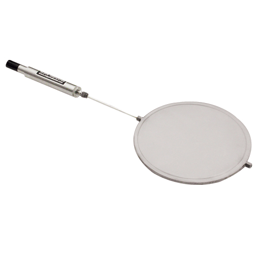
Total pressure is the intergranular pressure in the soil (effective stress) combined with the pressure of water in the voids between soil grains (pore water pressure). The pressure cell is formed from two circular plates of stainless steel whose edges are welded together to form a sealed cavity. The cavity is filled with a non-compressible fluid. The cell is installed with its sensitive surface in direct contact with the soil. The total pressure applied to that surface is transmitted to the fluid inside the cell and measured with a pneumatic or vibrating wire pressure transducer. | |||
| INSTALLATION | |||
Total pressure cells are typically embedded in fill or fixed to a structure. In fill, cells are often installed in arrays. Each cell is placed in a differentorientation and covered with hand-compacted fill. When mounted on a structure, the cell is placed into a recess so that its sensitive side is flush with the surface of the structure. The jackout total pressure cell is specially designed for installation in cast-in-place structures, such as diaphragm walls. Its name is derived from the use of a hydraulic jack that is activated to keep the cell in contact with the soil during concreting. | |||
| ADVANTAGES | |||
| Conformance | |||
| To minimize bridging effects, the total pressure cell has a low profile and a modulus similar to that of a typical soil. Fluid in the cell is de-aired to maximize sensitivity | |||
| Accurate Calibration | |||
| The total pressure cell is calibrated under fluid pressure in a custom-designed test fixture. | |||
| Pneumatic or Vibrating Wire | |||
| The total pressure cell is available in a pneumatic or vibrating wire version. | |||
| Manual or Automatic Readout | |||
| The vibrating wire version can be read with a portable indicator or a data logger. The pneumatic version must be read with a portable readout. | |||
| INSTALLATION OF THE JACKOUT CELL | |||
The jack-out cell is installed in the reinforcing cage, as shown in the drawing above. The signal cable and hydraulic hose are secured, and the cage is lowered into the slurry trench. When the cage is in position, the jack is activated and locked, forcing the cell into contact with the soil. The jack acts on the support plate, rather than directly on the cell, to prevent distortion of the cell. An equal force applied to the reaction plate. The trench is then concreted. In the illustration above, the jack has been activated, and the cell is in contact with the soil. Concrete is being delivered through a tremie pipe and will eventually displace the slurry. |  | ||
| SPECIFICATIONS | |||
| Resolution | 0.025% FS. | ||
| Repeatability | ±0.5% FS | ||
| Max. Pressure | 150% rated range | ||
| Fluid | Ethylene glycol, de-aired to 2 ppm | ||
| Dimensions |
| ||
| Weight | 3.2 kg (7 lb). | ||
| CAT. NO. | DESCRIPTION |
| SI52608220 | 3.5 bar (50 psi) Pressure Cell |
| SI52608230 | 7 bar (100 psi) Pressure Cell. |
| SI52608240 | 17 bar (250 psi) Pressure Cell. |
| SI52608250 | 35 bar (500 psi) Pressure Cell. |
| SI52618230 | 7 bar (100 psi) Jack-Out Cell |
| SI52618240 | 17 bar (250 psi) Jack-Out Cell |
| SI52618250 | 35 bar (500 psi) Jack-Out Cell |


Do you have a question?
min 10 ch