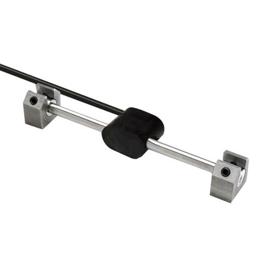
Arc-weldable strain gauges are used to measure strain in steel.
With the use of groutable anchors, the strain gauges can also be mounted to concrete surfaces. Typical applications include:
• Monitoring strain in structural members of buildings and bridges, during and after construction.
• Monitoring load in struts used to brace deep excavations.
• Measuring strain in tunnel linings and supports.
• Monitoring areas of concentrated stress in pipes.
| Operation | |||
| The strain gauge operates on the principle that a tensioned wire, when plucked, vibrates at its resonant frequency. The square of this frequency is proportional to the strain in the wire. The gauge is constructed so that a wire is held in tension between two mounting blocks that are welded to the structural member. Loading of the structural member changes the distance between the two mounting blocks and results in a change in the tension of the wire. An electromagnet is used to pluck the wire and measure the frequency of vibration. A change in strain is the difference between the current reading and the initial reading multiplied by a gauge factor. An electromagnet is used to pluck the wire and measure the frequency of vibration. Strain is then calculated by applying calibration factors to the frequency measurement. | |||
| Installation | |||
| The arc-weldable strain gauge is supplied with two mounting blocks. The mounting blocks are attached to a spacer bar and welded to the structural member. After the welds cool, the spacer bar is removed and the strain gauge is inserted in its place. The gauge is then connected to a readout and adjusted to measure tension, compression, or both. The strain gauge can also be used with groutable mounting blocks, which are anchored in holes drilled into the concrete structure. | |||
| Advantages | |||
| Permanently Attached Coils: The coils used to excite and read the vibrating wire are permanently attached to the gauge. This prevents accidental separation from the strain gauge body during installation. Install on Steel or Concrete: Use the weldable mounting blocks for steel and the groutable mounting blocks for concrete. Field Adjustable: The strain gauge can be adjusted so that most of its range is available to measure compression or tension, as required by the application. Reliable Signal Transmission: The arc-weldable strain gauge provides a strong signal which can be transmitted reliably over long distances with properly shielded cable. | |||
| ARC-WELDABLE STRAIN GAUGE | ||||
| VW Arc-Weldable Gauge | SI52640306 | |||
| Vibrating wire strain gauge for monitoring strain in steel structural members. Part number includes strain gauge with thermistor, and two weldable mounting blocks. Signal cable is ordered separately. | ||||
| Range | 3,000 microstrain. User can set tension to maximize range for the application. | |||
| Resolution | 1 microstrain with VW Indicator | |||
| Accuracy | ± 0.1% FS | |||
| Thermal Coefficient | 11ppm / °C | |||
| Length | 150 mm (5.875"). Long base gauges are available on special order | |||
| Mounting-Block | 38 x 10 x 19 mm (1.5 x 0.375 x 0.75") | |||
| INSTALLATION ACCESSORIES | ||||
| Installation Kit | SI52630330 | |||
| Kit includes two spacer rods, an allen wrench, and two spare set-screws. | ||||
| Spare Mounting-Blocks | SI52630350 | |||
| Two mounting-blocks with set-screws. Used if gauge is repositioned. | ||||
| Groutable Mounting Blocks | SI52640410 | |||
| Two mounting blocks with 3" long groutable anchors attached. Used to mount strain gauge to concrete. | ||||
| SIGNAL CABLE | ||||
| Signal Cable | SI50613324 | |||
| Shielded cable with four 24-gauge tinned-copper conductors and flexible polyurethane jacket rated to 80°C(176°F). | ||||
| Terminal Box for 6 sensors | SI57711606 | |||
| Terminal Box for 12 Sensors | SI57711600 | |||
| Terminal Box for 24 Sensors | SI97711624 | |||
| Provides terminals for signal cable from 6, 12, or 24 sensors. Sensors are selected by rotary switch. Dimensions of 6-sensor box are 240 x 190 x 120 mm (9.5 x 7.5 x 4.75"). Dimensions of 12 and 24-sensor boxes are 290 x 345 x 135 mm (11.5 x 13.5 x 5.25"). | ||||
| Universal Connector | SI57705001 | |||
| For terminating a single cable. Connector not required when sensors are connected to a terminal box, a data logger, or to the terminal posts on the VW Data Recorder. | ||||
| READOUT | ||||
| VW Data Recorder | SI52613500 | |||
| Jumper Cable for Terminal Box | SI52613557 | |||
| The VW Data Recorder displays VW sensor readings in Hz or H2/1000 and thermistor data in degrees C. It can also record the readings. The jumper cable is required when the VW Data Recorder is to be connected to a terminal box or to a connector attached to signal cable. | ||||
| DATA LOGGERS | ||||
| VW MiniLogger | SI52613310 | |||
| The VW MiniLogger is a compact, low-cost data logger for one sensor | ||||


Do you have a question?
min 10 ch