


Designed to save time, reduce water used, ensure accuracy and maintain sample integrity (sample may be used for slump and compression tests).
Features built-in, all-brass H-2785.DB super pump. Furnished with all necessary accessories for calibration and operation and carrying case.
Overall height: 20-1/2" (521mm).
Shipping wt.: 36 lbs. (16.4kg)
All our Type-B Concrete Air Meters feature our all-brass H-2785.DB Super Pump for reliability and faster operation.
All air meters meet ASTM C231; AASHTO T152.
Operation Instructions
- Fill base with a sample of fresh concrete, placing it in the base by vibrating or temping, in much the same manner as the concrete is to be placed on the job. Strike off the base, level full, with the bronze straight edge finish, Wipe top edge clean.
- Clamp cover on with petcocks open.
- Using rubber syringe, inject water through one petcock. Leave petcocks open.
- With built-in pump, pump up air to “initial pressure” line one gauge.
- Wait a few seconds for compressed air to cool to normal temperature and then bleeding off, as needed.
- Close both petcocks and press downs on “thumb lever” to release the air into the base. Hold thumb lever down for a few seconds, lightly tapping the gauge with the finger to stabilize the hand on the dial.
Do not tilt the meter at any time.
- Read percent of air in concrete on dial.
- Open the petcocks to release the pressure and then remove the cover.
Clean up base, cover and petcock openings.
To Check Calibration of Meter Gauge
- Fill the base full of water.
- Screw the short piece of straight tubing into the threaded petcock hole on the underside of the cover. Clamp cover on the base with the tube extending down into the water.
- With both petcocks open, add water with syringe through the petcock having the pipe extension below, until all air is forced out opposite petcock. Leave both petcocks open.
- Pump up air pressure to a little beyond the pre-determined initial pressure line. Wait a few seconds for compressed air to cool to normal temperature and then stabilize the gauge hand at the proper initial pressure line by pumping or bleeding off as needed.
- Close both petcocks and immediately press down on the thumb lever exhausting air into the base. Wait a few seconds until the hand is stabilized. If all the air was eliminated and the initial pressure line was correctly selected, the gauge should read 0%. If two or more tests show a consistent variation from 0% in the result, then change initial pressure line to compensate for the variation. Use the newly established “initial pressure” line for subsequent tests.
- Screw curved tube into the outer end of petcock and by pressing on thumb lever and controlling flow with petcock lever, fill the 5% calibrating vessel level full of water from the base. Release the air at the free petcock. Open the other pet cock and let the water in the curved pipe run back into the base. There is now 5% air in the base.
- With petcocks open, pump air pressure in exact manner as out lined in paragraph 4. Close petcocks and immediately press the thumb lever. Wait a few seconds for exhaust air to warm to normal temperature, and for the needle to stabilize. The dial should now read 5%.
- If two or more consistent tests show that the gauge reads incorrectly at 5% air in excess of .2% (or whatever is considered satisfactory),then remove gauge glass and reset the dial hand to 5% by turning the recalibrating screw.
- When gauge hand reads correctly at 5%, additional water may be withdrawn in same manner to check results at 10%, 15%, 20%, etc.
- The recalibrating screw is located in the center of the pointer.
Maintenance Tips
- Prompt cleaning with water of the air meter cover and pot, both inside and out will ensure a proper seal and volume are maintained.
- Periodic oiling of petcock screws will prevent them from seizing. WD-40 or a similar product is sufficient.
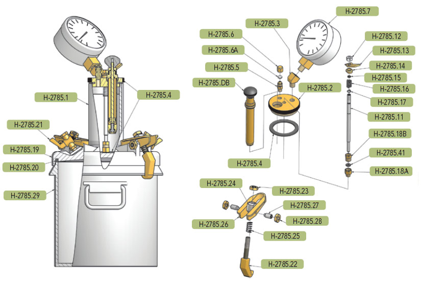
H-2786 Replacement Parts
- H-2785.1 — Pressure chamber
- H-2786.2 — Pressure chamber cap
- H-2785.3 — Pressure chamber elbow
- H-2785.4 — Pressure chamber gasket
- H-2785.5 — Air-release stem
- H-2785.6 — Air-release cap
- H-2785.6A — Release cap gasket
- H-2785.7 — Air meter gauge
- H-2785.11 — Needle valve stem
- H-2785.12 — Needle valve nut
- H-2785.13 — Needle valve lever
- H-2785.14 — Needle valve spacer
- H-2785.15 — Needle valve O-ring
- H-2785.16 — Needle valve spring
- H-2785.17 — Needle valve spring retainer
- H-2785.18A — Needle valve seat assembly
- H-2785.18B — Needle valve seat bushing
- H-2785.19 — Cover
- H-2785.20 — Cover O-ring
- H-2785.21 — Cover Petcock
- H-2785.22 — Clamp
- H-2785.23 — Clamp nut
- H-2785.24 — Clamp trunnion
- H-2785.25 — Clamp spring
- H-2785.26 — Clamp toggle
- H-2785.27 — Clamp toggle set screw
- H-2785.28 — Clamp toggle lock nut
- H-2785.29 — Base
- H-2785.41 — Needle valve seat gasket
- H-2785.51 — Pump piston O-ring
- H-2785.53 — Pump tube O-ring
- H-2785.DB — Super Pump Assembly
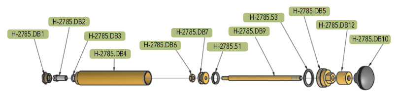
H-2785DB Super Pump Replacement Parts
- H-2785.DB1 — Valve nut
- H-2785.DB2 — Valve
- H-2785.DB3 — Valve O-ring
- H-2785.DB4 — Pump tube
- H-2785.DB5 — Pump cap
- H-2785.DB6 — Stem nut
- H-2785.DB7 — Pump piston
- H-2785.DB9 — Pump stem
- H-2785.DB10 — Pump handle
- H-2785.DB12 — Stem cap
- H-2785.51 — Pump piston O-ring
- H-2785.53 — Pump tube O-ring

Do you have a question?
min 10 ch