


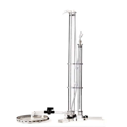
Tension Infiltrometers
- Soil Measurement System - 4884436
- On-site determination of hydraulic properties
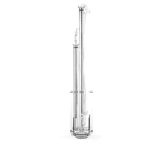
- Disc can be separated from the water tower or mounted under the water tower
- Requires low volume of water
One with an 8 cm base and one with a 20 cm base. With both infiltrometers data can be collected manually or with a datalogger
Both the 8 cm, and the 20 cm infiltrometers are available with nylon or stainless steel mesh screen membranes.
Tension infiltrometers are designed to measure the unsaturated hydraulic properties of soils. Water is allowed to infiltrate soil at a rate, which is slower than when water is ponded on the soil surface. This is accomplished by maintaining a small negative pressure on the water as it moves out of the infiltrometer disc into the soil.
In contrast, the saturated hydraulic conductivity of surface soils is often determined with single or double ring infiltrometers. With single or double ring infiltrometers, water at atmospheric pressure is allowed to infiltrate soil, initially fast, and at a slower rate once the open spaces in the soil fill up with water. When the rate of infiltration has stabilized, the infiltration rate is measured and used to compute the saturated hydraulic conductivity. However, because with ring infiltrometers water is ponded on the soil surface, a good portion of the water might infiltrate through cracks or wormholes, and a reduced amount will infiltrate through the soil matrix. By maintaining a small negative pressure on the water as it is infiltrating into the soil, water will not enter the large cracks or wormholes as much, but will infiltrate through the soil matrix. The higher the negative pressure applied to the water, the more soil pores below the soil surface are without water, and thus the soil becomes more unsaturated. With the tension infiltrometer one can determine the unsaturated hydraulic conductivity.
Features:
- On-site determination of hydraulic properties
- Disc can be separated from the water tower or mounted under the water tower
- Requires low volume of water
- Adjustable tension settings
- Flow rates are determined from changes in the water level inside the water tower
- Flow rates can also be determined from changes in the water level recorded with a datalogger, connected to a pressure transducer and attached to the water tower
- Polycarbonate and acrylic materials
Available with nylon or stainless steel mesh screen membranes
In summary, the SMS tension infiltrometer is designed to add water to soil at a range of tensions, which can be set by the operator of the instrument. By performing infiltration experiments at multiple tensions, one obtains data on the unsaturated hydraulic conductivity at the various tensions. The range of tensions that can be set is (for practical reasons) limited to tensions between 0 and –30 cm H2O. By setting the tension at or close to zero, one could obtain an infiltration rate that approximates the saturated hydraulic conductivity
There are a number of methods that can be used to calculate the hydraulic properties from the tension infiltration data. One method is based on the assumption of a log-linear relationship between tension and hydraulic conductivity, as first described by Gardner (1958). This is a valid assumption for the optimum tension range of the infiltrometer. This method can be found in the literature, and is described in detail in the manual that comes with the SMS infiltrometer.
Other methods to calculate the hydraulic properties from the infiltration data use inverse parameter estimation methodology to calculate the van Genuchten parameters (Simunek et al. 1994).
Field Set-up:
Before placing the infiltrometer on the site where a measurement is to be made, the site is leveled and cleaned of debris. A ring (either 8 or 20 cm in diameter- to be ordered separately from SMS) is placed on the leveled surface. The area within the ring is filled with fine sifted sand from the testing site or with silica sand (a few mm in thickness). The sand is leveled carefully and the ring removed. A perfect flat surface, 8 or 20 cm in diameter, is formed for placement of the infiltrometer. The sand layer should result in good contact between the base of the infiltrometer and the soil below.
For the 20-cm infiltrometer only, make sure the area where the water tower is going to be placed should be at the same elevation as the top of the sand layer for the disc. One can accomplish this by adding or removing soil from this area. It may be convenient to use a carpenters level to make sure these two surfaces are at the same level. Prepare the spot for the water tower using the carpenters level to ensure the correct height of the water tower, before removing the soil ring.
By raising or lowering the tube in the bubble tower, the tension that will be maintained at the bottom of the base plate can be set. The maximum tension is generally less than 30 cm. Many researchers start with the highest tension (often 20 cm). One should note that at the highest tension, the hydraulic conductivity is the lowest, and thus it may take some time for the instrument to start "bubbling". If it takes too long for bubbles to appear one may want to reduce the initial tension. Some investigators moisten the soil surface with a very fine spray.
Data Collection:
The SMS infiltrometers are designed to collect data manually or automatically. Data are collected manually by recording the water level in the supply tower over time. One simply reads the water level in the supply tower at fixed time intervals (i.e. one minute: more frequent early on and less frequent during the steady state phase),and records the information together with the time passed since the start of the experiment.
For multiple sites, it is advantageous to use a datalogger to record the data. The water level in the supply tower is then recorded by installing a 1 psi (66 mbar) differential pressure transducer connected to a suitable datalogger. The pressure difference between the air in the top of the water tower and the water near the bottom of the water tower is recorded. With such a pressure transducer system, the effects of air bubble induced noise are reduced. As the water level in the water tower decreases (as it infiltrates into the soil),the negative pressure in the water tower becomes less negative. Thus, the pressure transducer output is linearly related to the water level in the water tower. Output recorded from the pressure transducer therefore provides a continuous record of the volume of water entering the soil as a function of time. A continuous record with frequent readings is important if one is interested in the early, transient infiltration behavior.
Water level data can be recorded with a Campbell Scientific datalogger or similar device. Dataloggers that provide a constant exitation voltage (between 2.5 and 12 volts DC) to the transducer and record the millivolt output from the SMS pressure transducers with an accuracy of at least 0.1 millivolts can be used.
| Specifications |
20 cm Model |
8 cm Model |
| Diameter Disc | 20 cm | 8 cm |
| Inside Diameter Water Reservoir | 5.1 cm | 2.54 cm |
| Inside Diameter Bubbling Tower | 2.54 cm | 2.54 cm |
| Length Water Reservoir | 81 cm | 81 cm |
| Bubbling Pressure Membrane | 30 cm H20 | 30 CM H20 |
| Carrying Case Dimensions (optional) | 28cmx36cmx107cm | 28cmx36cmx107cm |
| Pressure Transducer | 1 psi (67 cm H20) | 1 psi (67 cm H20) |


Do you have a question?
min 10 ch